Stefan F. Dieffenbacher, M.B.A.
Founder and CEO of Digital Leadership
While a physical paper schematic is the ultimate tool, you can easily navigate the Wannien 101V0 board by dividing it into functional blocks. If you are looking at the traces on the board or a diagram, it follows a standard SMPS progression. 1. The Input Protection and EMI Filter Stage
Low-ESR electrolytic capacitors smooth the low-voltage DC rails (typically +5V, +12V, or +24V) for final delivery to the mainboard or backlight inverter. Technical Schematic Trace (Component Layout)
Power enters the board through an AC inlet. It immediately passes through a protection and filtering network designed to suppress electromagnetic interference (EMI) and protect against voltage spikes:
The main filter capacitor on the primary side can hold upwards of 400V DC long after the power supply is unplugged. Always manually discharge this capacitor using a high-wattage resistor (e.g., a 2K ohm 5W resistor) before touching the board. Never short it with a screwdriver, as this can damage components and cause dangerous sparks. Step 1: Visual Inspection Examine the board under bright light. Look for: Bulging or ruptured electrolytic capacitors. wannien 101v0 power supply schematic free
From that day on, Alex and Mr. Wannien maintained a close relationship, collaborating on projects and pushing the boundaries of what was possible in electronics. The Wannien 101V0 power supply became a symbol of their partnership, representing the fusion of innovation, expertise, and mentorship.
The Wannien 101V0 is a standard switched-mode power supply (SMPS). It converts high-voltage alternating current (AC) from a wall outlet into stable, low-voltage direct current (DC) required by sensitive digital logic circuits. The board is divided into two distinct regions separated by an isolation barrier: the primary (hot) side and the secondary (cold) side. 1. AC Input and EMI Filtering (Hot Side)
If the original switching transistor is blown and its part number is unreadable, trace the voltage layout. Most boards of this form factor utilize standard N-channel MOSFETs rated for 600V to 650V and 4A to 7A (e.g., 4N60 or 7N60). Ensure the pinout configuration matches. While a physical paper schematic is the ultimate
"Ah, you're looking for the schematic," Mr. Wannien said, as if reading Alex's mind. "I'm afraid I don't share my designs freely. However, I can offer you a chance to learn from me, and perhaps, one day, you'll be able to create something as remarkable as the 101V0."
Visually inspect capacitors for bulging tops or leaking fluid. Replace them with high-quality, low-ESR capacitors rated for 105∘C105 raised to the composed with power C Failed Optocoupler or TL431
Search online repository forums dedicated to monitor and TV repairs. Websites like Elektrotanya, Badcaps.net, and Service-Manual.net host thousands of free schematics. Enter the board number 101V0 or look up the model number of the monitor or device the board was pulled from. 4. Common Failures and Troubleshooting Steps The Input Protection and EMI Filter Stage Low-ESR
Flyback converter topology (common for power supplies under 150 Watts) 2. Block Diagram Circuit Analysis
This comprehensive guide breaks down the Wannien 101V0 power supply architecture, identifies common failure points, and explains how to diagnose the board even without a factory-printed circuit diagram. Understanding the Wannien 101V0 Architecture
: A detailed PDF version of the Wannien 101V0 Power Supply Schematic is available on Scribd . For specific troubleshooting questions, experts on JustAnswer have previously addressed repairs for this specific board. Wan Nien 101V0 Power Supply Schematic - Expert Q&A
Let’s find the best solution for your business to grow and scale sustainably!
We will uncover your current business situation and goals and provide you with a bespoke solution that helps you drastically grow your business working with us.


Founder and CEO of Digital Leadership
Read the reviews and make sure that this is not a waste of time, but a super effective tool.
![]()
Let’s find the best solution for your business to grow and scale sustainably!
Let’s find the best solution for your business to grow and scale sustainably!
We will uncover your current business situation and goals and provide you with a bespoke solution that helps you drastically grow your business working with us.

Founder and CEO of Digital Leadership
Read the reviews and make sure that this is not a waste of time, but a super effective tool.
Let’s find the best solution for your business to grow and scale sustainably!

On this call, we will uncover your current business situation and goals and talk about how to drive change and solve your need.
![]()
Welcome to our scheduling page.
Choose the meeting type that applies to your needs and schedule a time to meet with someone from our team.
We look forward to speaking with you soon!
In a uniquely designed 60 or 90 minute session*, we will …
Based on the Blueprinting session, you will receive a tailored blueprint that aligns with your objectives, vision and goals, ensuring that your initiative is a success from start to finish.

In this session, you will be working together with Patrick Zimmermann, Associate Partner for Customer Experience
In a uniquely designed 60 or 90 minute session*, we will …
Based on the Blueprinting session, you will receive a tailored blueprint that aligns with your objectives, vision and goals, ensuring that your initiative is a success from start to finish.

In this session, you will be working together with Dr. Andreas Rein, Partner at Digital Leadership for Culture & Org Change
In a uniquely designed 60 or 90 minute session*, we will …
Based on the Blueprinting session, you will receive a tailored blueprint that aligns with your objectives, vision and goals, ensuring that your initiative is a success from start to finish.

In this session, you will be working together with Sascha Martini, Partner at Digital Leadership for Innovation and Digital Transformation
In a uniquely designed 60 or 90 minute session*, we will …
Based on the Blueprinting session, you will receive a tailored blueprint that aligns with your objectives, vision and goals, ensuring that your initiative is a success from start to finish.

In this session, you will be working together with Stefan F. Dieffenbacher, Founder of Digital Leadership
Stefan is a global thought leader in the innovation space
In a uniquely designed 60 or 90 minute session*, we will …
Based on the Blueprinting session, you will receive a tailored blueprint that aligns with your objectives, vision and goals, ensuring that your initiative is a success from start to finish.

In this session, you will be working together with Adam D. Wisniewski, Partner for IT Strategy & Business Alignment
Let’s find the best solution for your business to grow and scale sustainably!

On this call, we will uncover your current business situation and goals and talk about how to drive change and solve your need.
![]()
Welcome to our scheduling page.
Choose the meeting type that applies to your needs and schedule a time to meet with someone from our team.
We look forward to speaking with you soon!
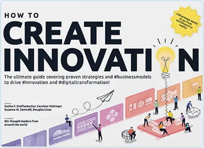 Book How to Create Innovation